
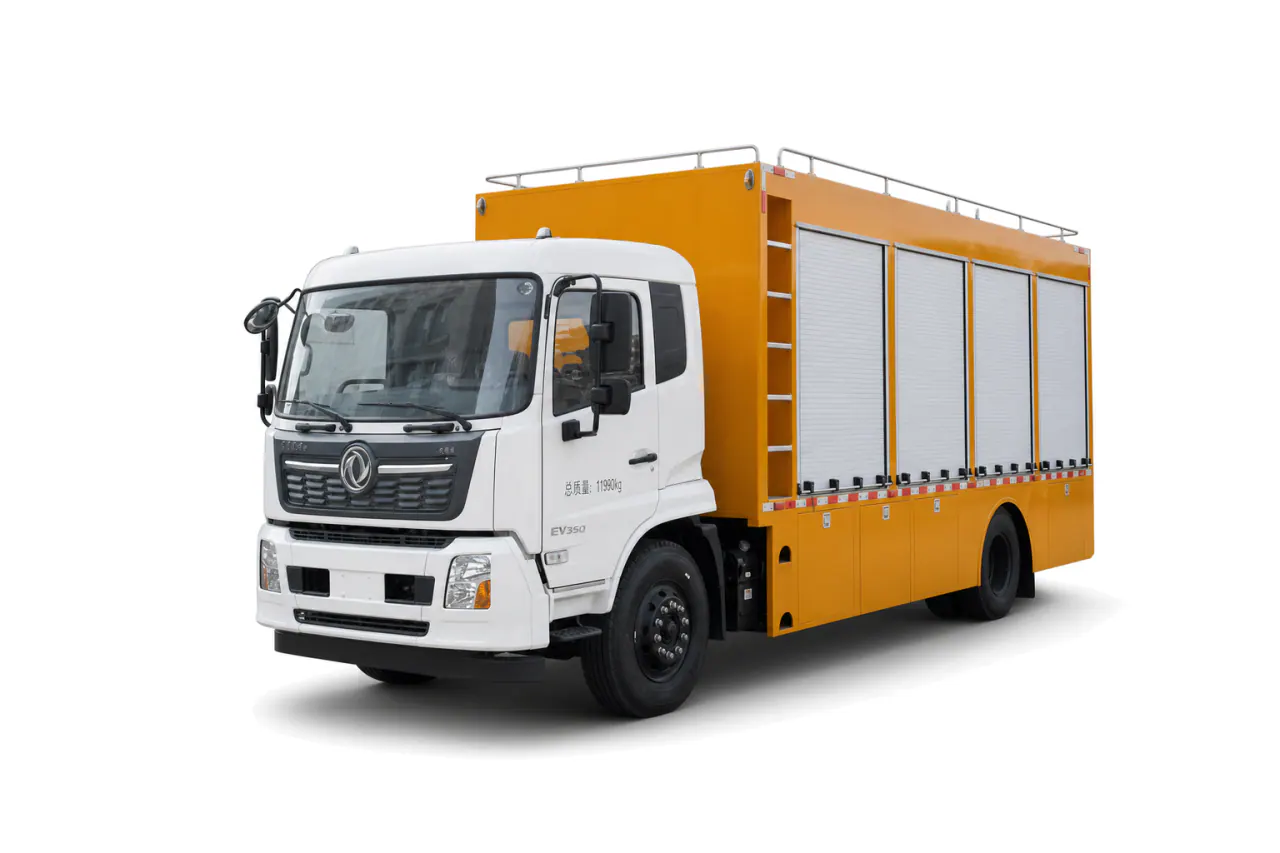
Mobile Drainage Pump Truck
Choose pump flow at the total dynamic head your drainage job requires. Account for solids, intake conditions, the hose route and discharge point, as well as runtime and maintenance access.
Size flood-response vehicles for the required pump duty and field conditions. Plan the hose route and discharge point, with enough power and maintenance support for the operating duration.
Prepare this mission briefStart with the main job the vehicle must do. Include supporting vehicles when the response plan gives them a specific role.
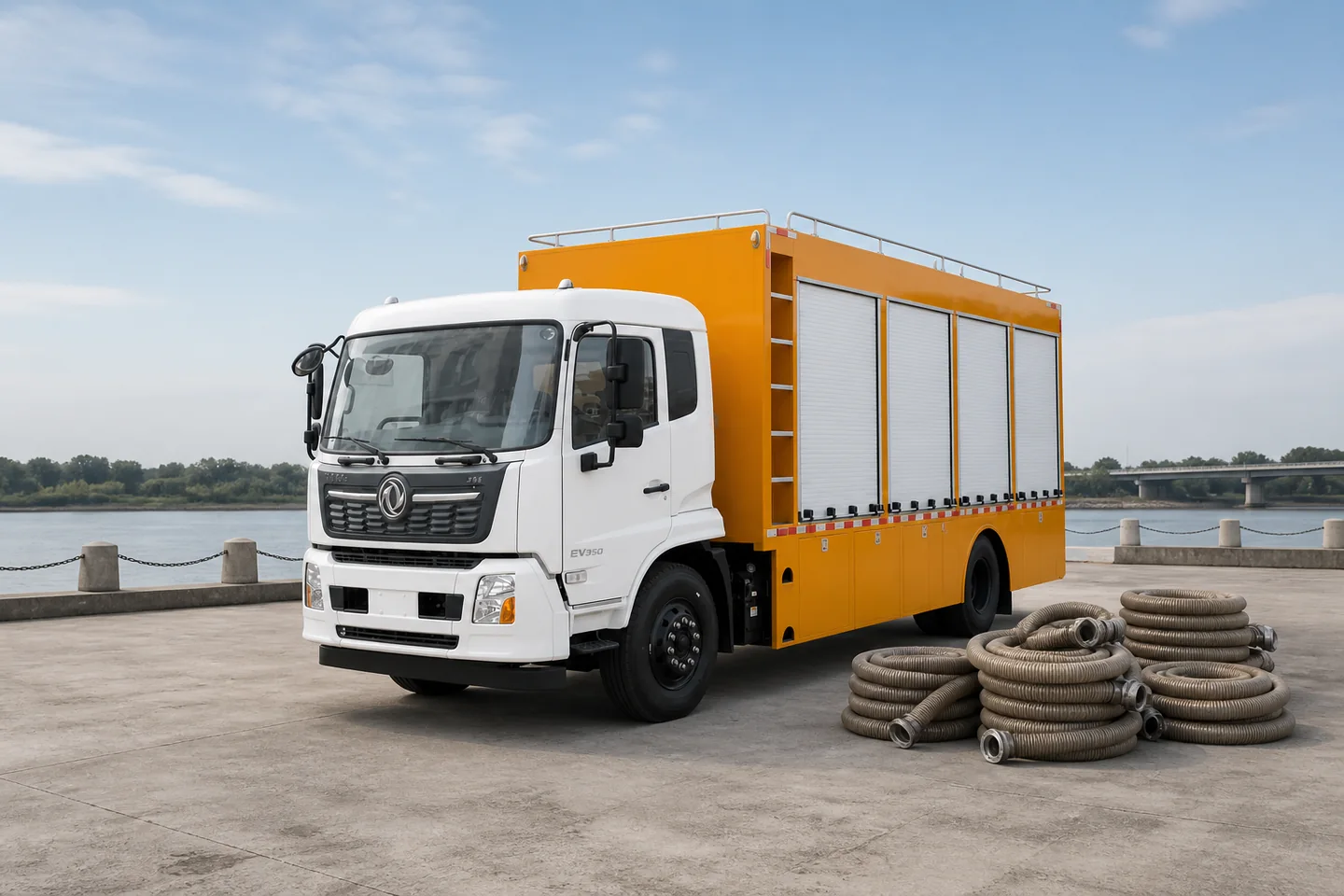
Choose pump flow at the total dynamic head your drainage job requires. Account for solids, intake conditions, the hose route and discharge point, as well as runtime and maintenance access.
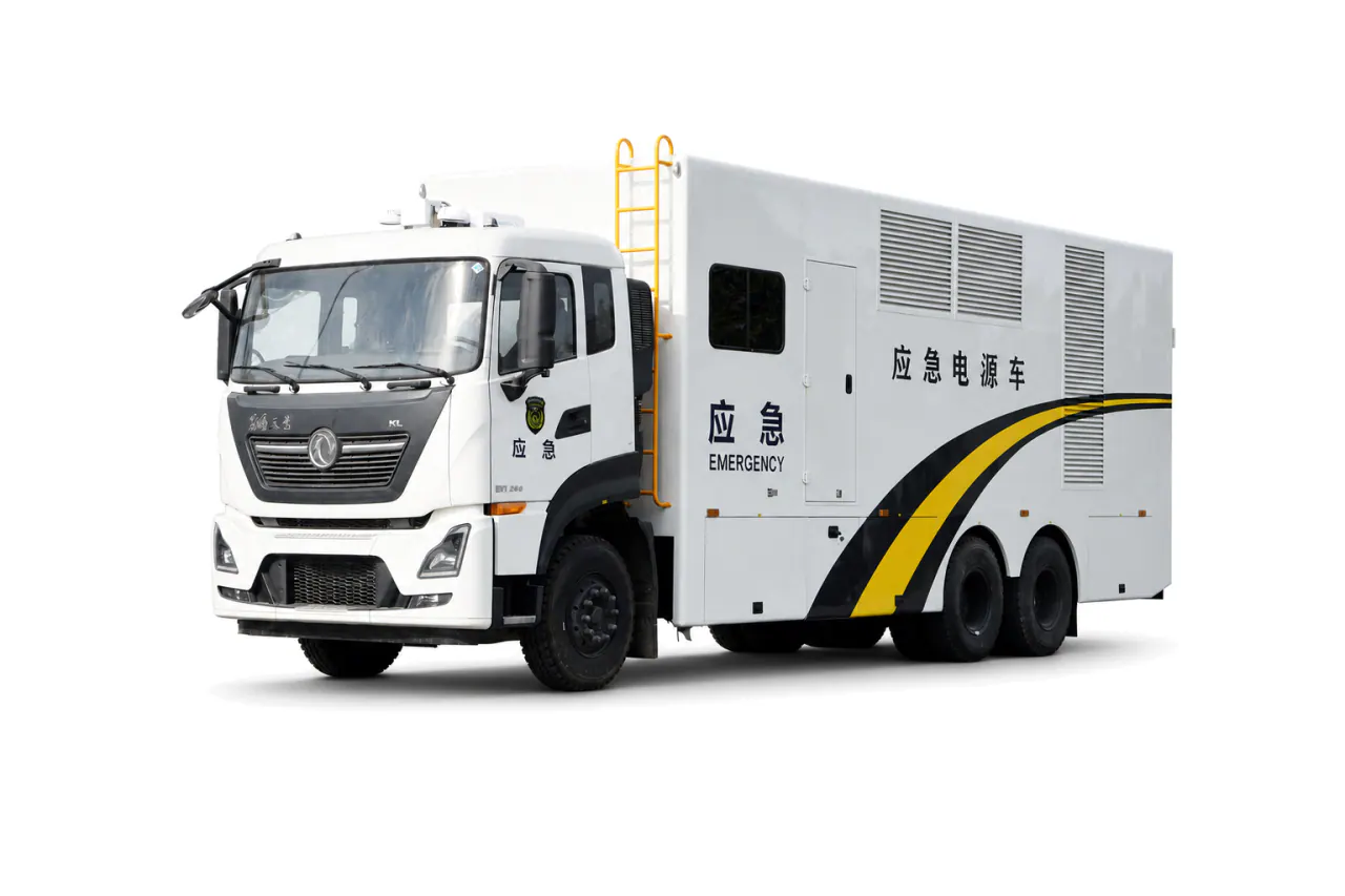
Use the electrical load schedule to specify voltage, protection and runtime. The power truck also needs suitable distribution connections, ventilation and fuel provision, with load-step tests agreed before acceptance.
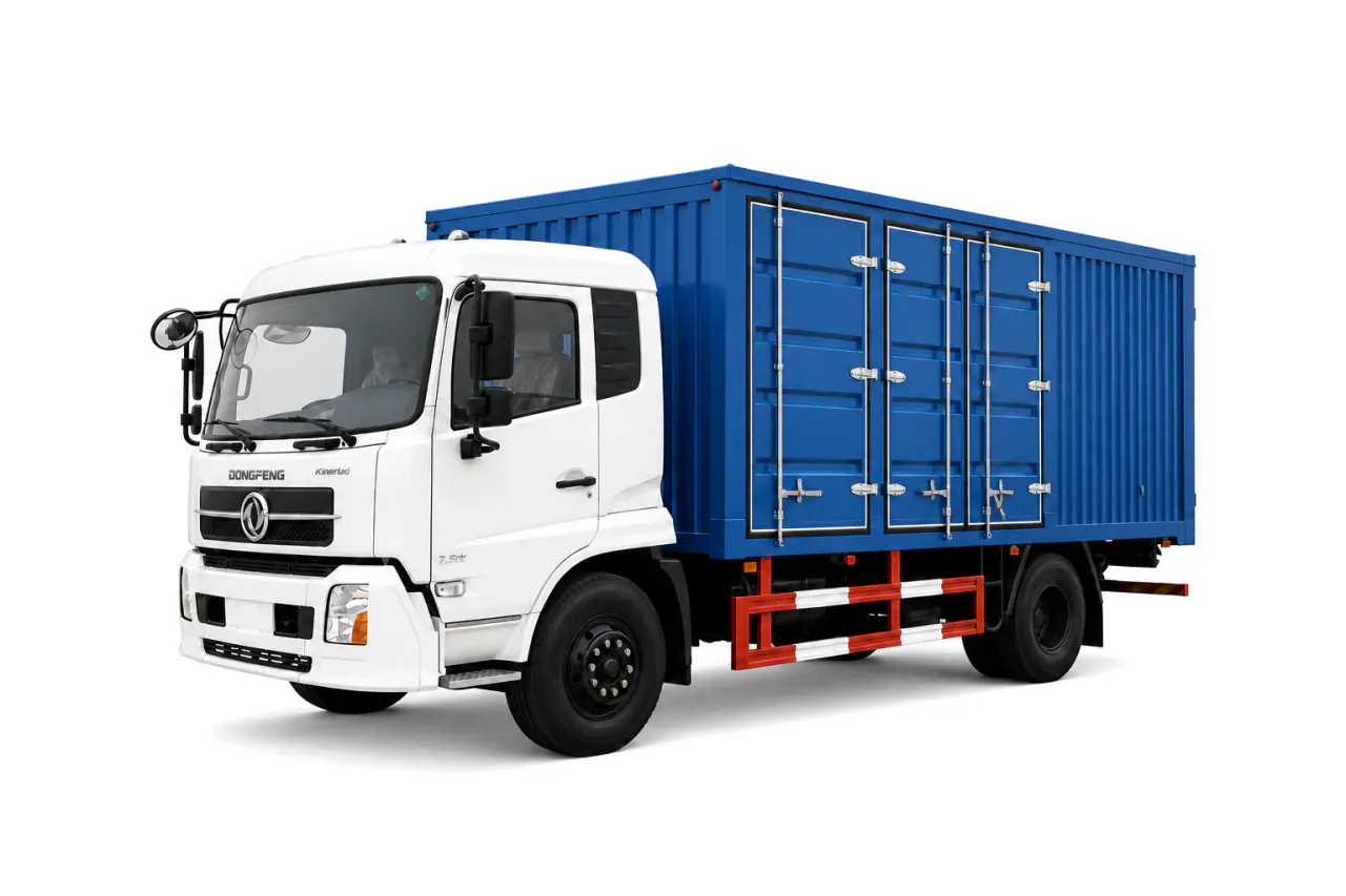
Start with the repairs the workshop truck will carry out in the field. Allow for tools, a workbench, air, welding and power, with enough storage, payload and access for servicing.
Specify drainage flow at the required head, because a free-flow pump figure does not describe the installed duty. With the site conditions, deployment duration and maintenance plan defined, KEEYAK can configure the drainage, power and workshop vehicles needed.
| Decision | Why it matters | What to provide |
|---|---|---|
| Flow and head | Lift, friction, hose diameter, solids and outfall determine useful discharge. | Provide target flow at total dynamic head, intake and hose route.Retain: Duty point, pump record and agreed test condition. |
| Power and duration | Starting loads, fuel, lighting and cooling determine sustained operation. | List connected loads, runtime, fuel and operator access.Retain: Electrical load schedule, protection and runtime record. |
| Support scope | Workshop or command support is useful only when duration and site spread justify it. | State sites, shifts, parts, tools and coordination needs.Retain: Fleet brief, equipment inventory and handover plan. |
Choose the pump truck from the water movement task, with required flow stated at total dynamic head. Describe the intake and solids present, then map the hose route to the discharge point. To decide whether mobile power is needed, calculate continuous demand and starting loads, including auxiliary equipment. Add a workshop or command vehicle only if the response duration or spread of sites justifies its role.
Check how the pump and generator will operate with the hoses, couplings and guards, including access around the vehicle. The rated capacity alone cannot show the effect of an unsuitable intake, a long hose route or a restricted outfall.
Choose equipment for the agreed work, then specify its connections and the records needed to check it.
Use these steps to prepare the configuration and acceptance brief, not as a field operating procedure.
Estimate the water movement task and required operating duration.
Set the target flow at total dynamic head.
Describe solids, intake depth, contamination and water variation.
Map the full hose route, crossings and permitted discharge point.
Test pump duty, starting load, protection, guarding and runtime at agreed conditions.
This is a planning example, not a standard disaster-response package. Establish the flood locations and water volumes, then the pumping distances. Set vehicle quantities against grid availability and crew capacity, with fuel and maintenance support accounted for.
Add these vehicles only where the response plan identifies a separate duty.
Emergency Command VehicleClass B Emergency Monitoring AmbulanceUse only where the intended task, equipment configuration and operating conditions are documented.
Integrated WreckerReview the relevant selection and procurement guidance before finalizing the brief.
Emergency Support Vehicle SpecificationEmergency Response Fleet PlanningBring the operating duty, equipment scope and destination requirements into one configuration brief.
Send your mission requirements to our team.