
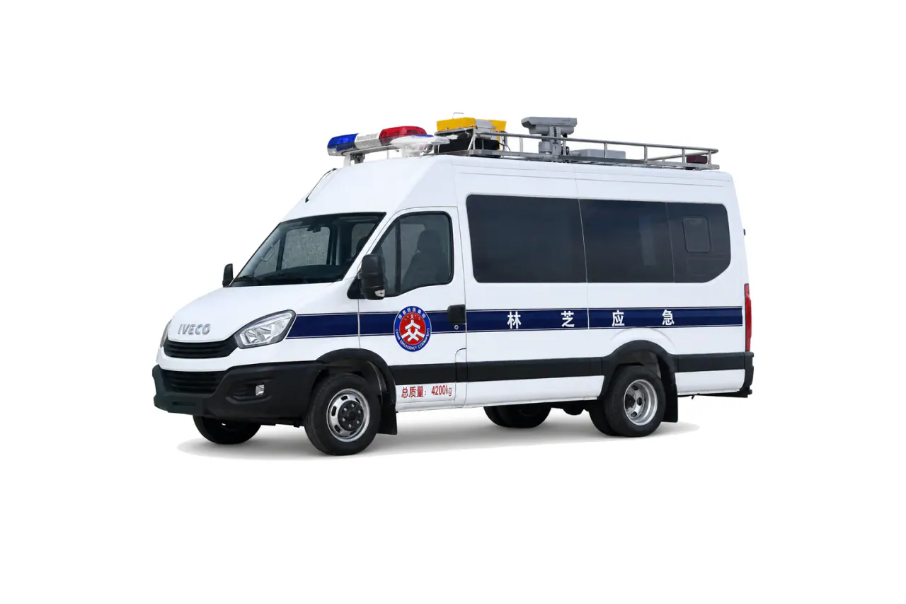
What defines a command vehicle configuration?
Map how the agencies and operators will work during an incident, including the information they need and the deployment steps. Use that workflow to specify the workspace and communications equipment, then define the antennas and power supply required.
Map people and decisions first
Begin with the agencies and functions that will use the vehicle. Place operators where supervisors can see them and allow space for briefings. Work through shift changes and handovers, including who receives information and who is allowed to see it. Specify where decisions will be recorded.
Size the body and furniture so operators can hear one another, see displays and reach controls while carrying out that workflow. Show aisle clearance, seating and storage on the drawing, with access routes and emergency exits.
Define the communications architecture
Create an interface schedule for radio bands, network equipment, dispatch systems, cameras, displays, recording, antennas and external feeds. Mark customer-supplied equipment, supplier-installed equipment and interfaces that remain open. State connector, cable, mounting and commissioning responsibility.
Separate internal collaboration from external connectivity. The vehicle may need local operation when a public network is unavailable, but the exact resilience requirement must come from the agency’s operating plan.
Build the power and cooling schedule
Prepare a load schedule for the communications equipment and displays, then add lighting and outlets. Include HVAC and auxiliary equipment, distinguishing continuous and intermittent demand from starting loads. Assign each operating mode to shore power, a generator, a UPS or batteries; do not assume one source can supply them all. Account for heat loads and ventilation, and show cable entry and earthing on the layout with enough room for servicing.
Review setup and pack-down. Antennas, masts, stabilizers, external cables, steps and awnings can expand the operating footprint and create dependencies on ground, weather and traffic control.
Information to include in the RFQ
- Agencies, operator count and command workflow
- Workstations, displays, storage and briefing space
- Radio, network, video, antenna and external interfaces
- Connected loads, backup power and HVAC conditions
- Deployment footprint, security and access controls
- Integration tests, documentation and operator handover
Inspection and acceptance
Run a deployment exercise using the approved sequence. Check the workstation layout and test communications interfaces through the displays. During the exercise, verify power transfer and UPS behavior, then HVAC and lighting. Inspect cable routing and security before checking pack-down. If an external service is unavailable, record the resulting test limitation; that function has not passed.
Separate travel seats from parked work positions
The main-site description distinguishes approved travel seating from operator positions used when parked. Show both on the layout; a meeting position is not automatically an approved passenger seat. Check circulation with the intended workstations occupied. [2]
Identify the network, equipment and interface used in each acceptance demonstration. A working display does not prove that agency radios or dispatch systems can exchange information. Record substitute test setups and the live-system checks still required. Inventory removable equipment and serialized accessories at handover, keeping access credentials out of publicly shared documents and photographs. [2]
Prepare the communications scope
Compare the command and communication vehicle range, then capture workstation, device and utility interfaces in the vehicle RFQ. Keep customer-supplied systems and integration responsibilities explicit.
Evidence boundary
This guide supports planning. The command vehicle specifications do not establish network availability, interoperability, runtime or destination approval. Confirm final interfaces and tests with the participating agencies and project documents.
Review checklist
- An operator and agency workflow
- An interface and electrical schedule
- A deployment, system-test and handover plan
Sources
- [1]
- [2]Emergency Command Vehicle | KEEYAK special vehiclesKEEYAK · reviewed 2026-09-07Source retained on file
Each source supports only the planning statement that cites it. For the selected vehicle, confirm the destination law and applicable editions, along with the evidence required for that project and jurisdiction.